Pressure Testing
Pressure testing is a process of checking the integrity of the piping system (leak tightness and strength to withstand working pressure) by pressurising it with a testing fluid and checking for leaks. The test pressure is usually 1.5 times the working pressure and the test fluid is either the system fluid or a fluid suitable for testing and which does not contaminate the system. A system is said to be successfully pressure tested if it can hold the test pressure for a certain minimum time period with no visible leaks or pressure loss.
A hydraulic pressure testing circuit mainly consists of the following components:-
1. Hydraulic Power Pack or TMI Testing/Flushing Unit (FL-200-50)
2. Test Fluid Filling Equipment or TMI Testing/Flushing Unit (FL-200-50)
3. Pressure Testing Materials (Gauges, Valves, Blanks, Interconnection Hoses)
The system is filled with the testing fluid by either an equipment which acts both as a Power Pack and Filling System (like TMI Testing/Flushing Unit) or will be done by a standalone equipment which can be the system’s Hydraulic Power Unit (HPU) itself. The system is fitted with pressure gauges, drain & vent valves and with suitable isolation/connecting components to carry out the testing. The pressure in the system is built up by the Hydraulic Power Pack (HPP) upto the test pressure. The system is deemed pressure tested if there are no visual leaks or pressure drop for a specific time period.
Pressure Testing is a very critical process and hence following standard established procedures as follows is very important to ensure a safe and effective execution -
- All testing equipment should be in good working condition.
- All measuring instruments should be properly calibrated with a valid calibration certificate.
- It should be ensured that all activities preceding to pressure test is checked and duly certified by respective authorities, for example drawing check, fabrication check, routing clearance etc.
- The pressure testing activity has to be documented in a Pressure Testing Report which should capture enough information in order to rule out any ambiguities in verification later on. Details of the system, pressure, testing and measuring equipment, drawing number etc. should be included in it.
- The testing area has to be secured and the personnel carrying out the activity should exercise extreme caution. All permits should be obtained, the test area has to be clearly identified with safety boards and segregated with red and white tape barriers.
- Caution Boards in a language known to the personnel at the site (ideally a local language and English) to be shown at strategic locations until the pressure test is concluded.
- The pressure test system should consist a drain valve and a pressure gauge at the lowest point, and one more pressure gauge and a vent valve at the highest point.
- System should be completely filled with test fluid and any air-trap should be eliminated with the help of air vent valves prior to building pressure.
- The test pressure should at least be 1.5 times the working pressure of the system or else as specified. The pressure build up should ideally be done in stages, an initial pressure of 25 bar can be given and held following which the pipes are checked, the remaining pressure can be built up incrementally in 2-3 stages. After every pressure build up stage, the line should be checked for visual leak and pressure loss before proceeding to the next stage.
- The pressure should be held for at least 15 mins with no decay of pressure more than 5% and no visible leaks.
Explanation with Example
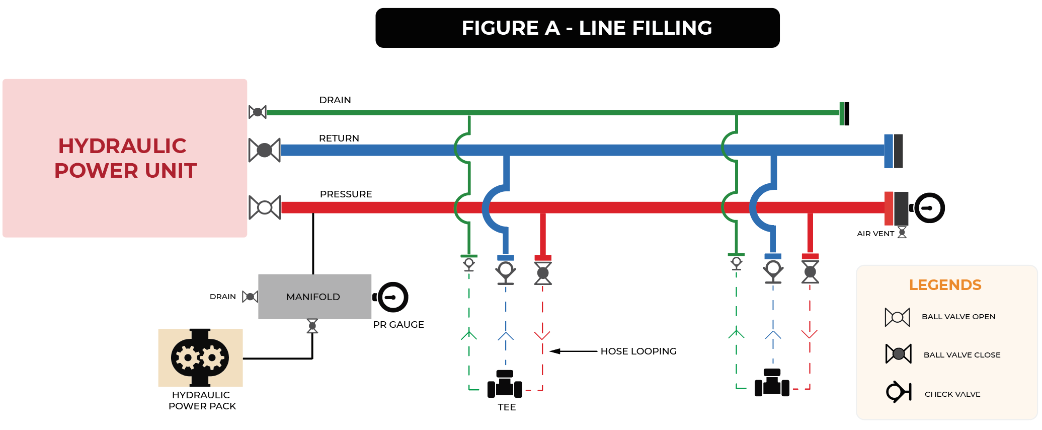
- Fill the entire system with oil.
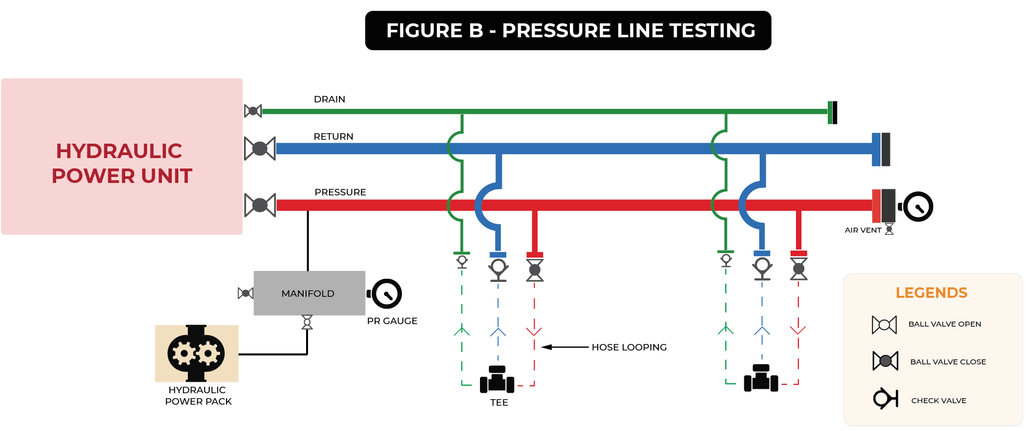
- Isolate and test the pressure line.
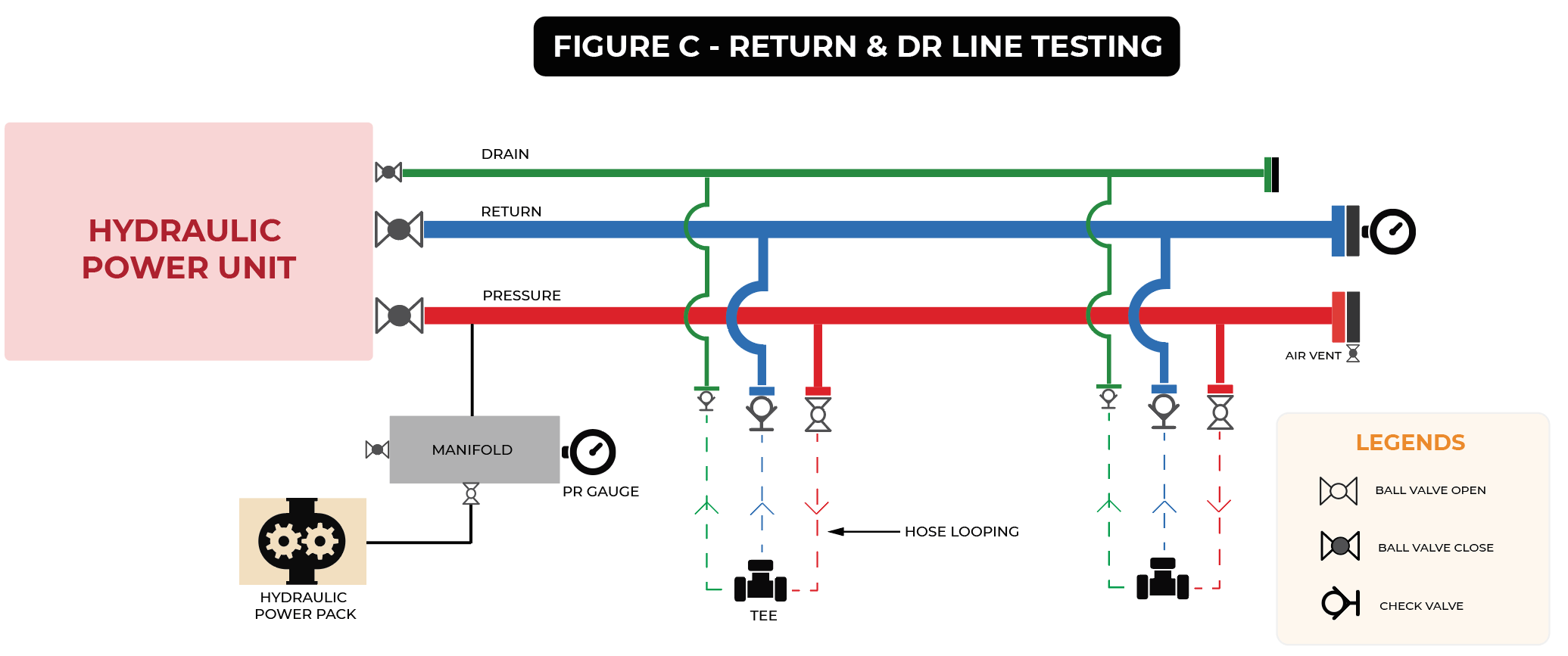
- Open the Isolation valve to integrate the pressure line with the rest of the system and pressure test the whole system to the Return and Drain Line Test Pressure. Thus testing the return and drain lines.
After filling the entire line as shown in Figure A, the pressure line will be tested by isolating it from the return and drain lines as shown in Figure B since it has a greater test pressure .
The line is pressurized and checked for leaks by considering the following points-
- Visual check of the joints (flanges, fittings) to spot any leakages.
- Check for pressure loss on the pressure gauge to spot any pressure loss. If there is a pressure loss, it should not exceed 5%.
If there are no leaks or pressure drop, the pressure is released using the drain valve and the tap-off ball valves are opened to re-connect the pressure line. Since the return and drain lines have lower pressure than the pressure line, they can be pressure tested along with the pressure line. Hence, the line is again pressurized to the test pressure of return and drain lines as shown in Figure C. If it passes the check, the pressure is released and the system is successfully pressure tested. The pressure test report has to be filled and has to be duly signed by the customer.
Download the E-Book
DOWNLOAD E-BOOK
