GMS Evolution - Hydraulic Piping for Cantilever and Drill Floor Assembly, UAE
Case Study: GMS Evolution - Hydraulic Piping for Cantilever and Drill Floor Assembly: UAE
A leading piping contractor gave the responsibility of estimation, supply and supervision of hydraulic piping for GMS Evolution. Being a Self-Propelled Self-Elevating DP2 Jackup Barge, it had capabilities like DP 2 positioning, accommodates 150 personnel and multi cranes including one of 200 tonnes capacity. With a self-propelled jack-up, it houses a retractable cantilever and workover unit.
The project involved implementation of Non Welded Hydraulic / High Pressure Piping for Main HPU distribution system and Cantilever Ring line system. Top drive system, Travelling Assembly, Main rider winch, Iron rough neck, Pipe handling system, Hydraulic Cathead were the major equipment involved in these systems.
Project Details were as follows:-
The total length of all the piping was about 1100 m.
The project scope of work was as follows:
A leading piping contractor gave the responsibility of estimation, supply and supervision of hydraulic piping for GMS Evolution. Being a Self-Propelled Self-Elevating DP2 Jackup Barge, it had capabilities like DP 2 positioning, accommodates 150 personnel and multi cranes including one of 200 tonnes capacity. With a self-propelled jack-up, it houses a retractable cantilever and workover unit.
The project involved implementation of Non Welded Hydraulic / High Pressure Piping for Main HPU distribution system and Cantilever Ring line system. Top drive system, Travelling Assembly, Main rider winch, Iron rough neck, Pipe handling system, Hydraulic Cathead were the major equipment involved in these systems.
Project Details were as follows:-
Sl No |
Line Name |
Line Size |
Line Pressure |
TMI Technology Used |
|---|---|---|---|---|
1 |
Main HPU Distribution Lines |
97 x 12 mm, |
5000 PSI |
Retain Ring Flange System |
2 |
Cantilever Ring Line System |
60 x 5 mm, 60 x 4 mm, 50 x 5 mm |
3000 PSI |
37 Degree Flare Flange System |
3 |
Equipment Lines |
38 mm, 35 mm, 30 mm, 28 mm, 25 mm, 22 mm, 18 mm, 12 mm |
upto 5000 PSI |
Pyplok® |
The total length of all the piping was about 1100 m.
The project scope of work was as follows:
- Design / Engineering: Based on the preliminary information that we received from the end user like P&ID of the system, tentative routing plan, equipment end connections etc. we arrived at the BOM. The creation of the BOM was solely relied upon Chase Resource by the customer. The routing changes are done based on the mutual understanding between the customer designers and our field personnel to achieve the accuracy and aesthetic look.
-
Pipe Fabrication: After finalising the routing plan and getting the design approval from the client for fabrication, our site team consisting of 1-2 lead technicians and customer’s installation team started fabrication of the pipe spools at a workshop arranged near to the vessel.
All the pipe spools were fabricated at the site workshop and were handled such that contamination of the pipe/ tube by environmental dirt, moisture, rust, pollution or by any other means was avoided. After fabrication, each pipe spool was inspected and certified by yard QC.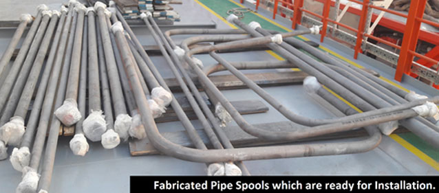
-
Installation: The installation of the QC Inspected Fabricated pipe spools was done according to the piping layout and by following the Tube-Mac Installation Standards and Procedures Manual. The Erection was closely monitored by Tube-Mac and Chase Resource Technicians.
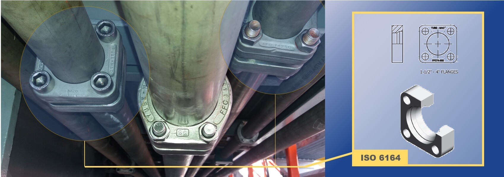
TMI’s Retain Ring and 37 Degree Flare ISO 6164 Square flanges with efficient design and for pressures upto 5000 psi
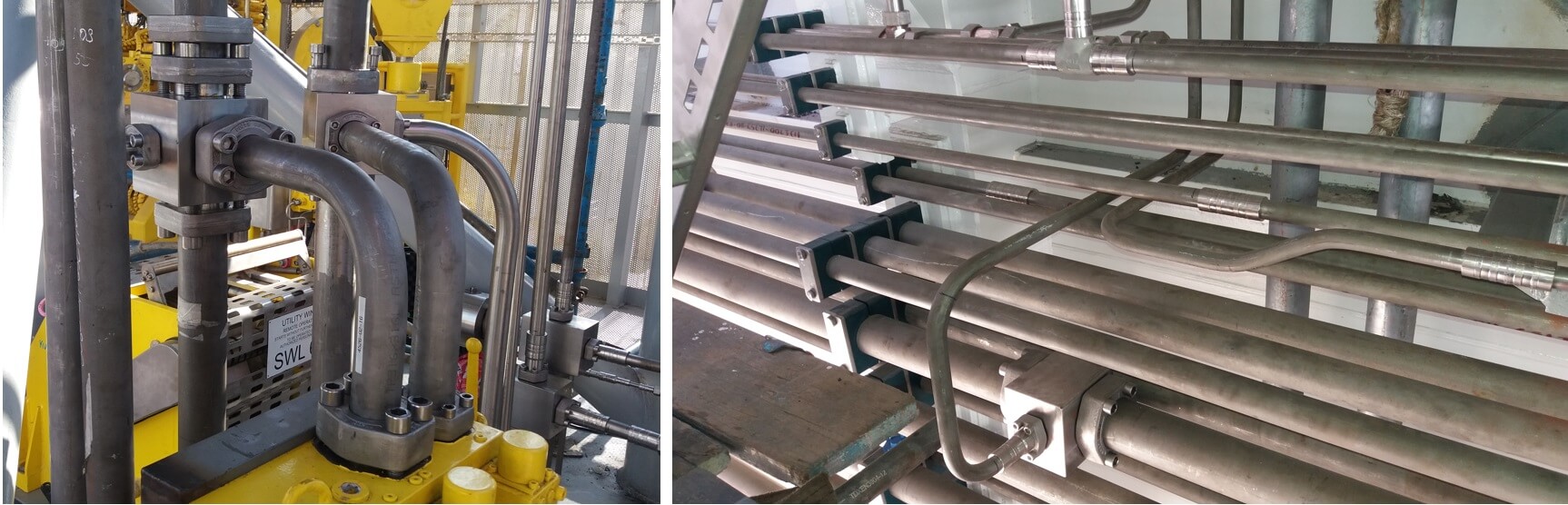
Bending utilised at every possiblity to reduce costs and potential leak paths
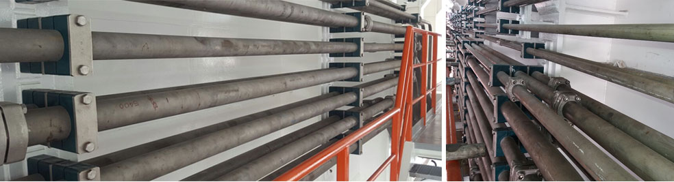
The pipe supports were installed as per the standard requirement and design provided by the design team.
The piping joints were torqued to the required value after completion of the pipe erection and before doing the pressure test.
- Pressure Testing: The installed pipes were Pressure tested to 1.5 x system working pressure with hydraulic oil and was witnessed.
- Flushing: Flushing was done and the required cleanliness value was achieved without any hassles (which is a typical characteristic of any project installed with TMI Non-Welded Piping).
- Commissioning and Handover: After completion of flushing activity, the flushing loops were dismantled and reconnected to the respective equipment ports. The reassembled joints were re-torqued to the required value and the system equipments were run. The customer positively acknowledged the job with signed reports after successful commissioning.
Download the Project E-Book
DOWNLOAD E-BOOK
