Hydraulic Piping for Block and Head Test Rig - Fatigue Lab, India
Case Study: Cummins- Hydraulic Piping for Fatigue Lab: Pune, India
Cummins, the leading engine manufacturer was setting up a Fatigue Laboratory in the newly constructed Applied Mechanics Lab at their R&D Facility in India. They needed hydraulic piping for their Block and Head Test Rig. The test rig produced a lot of vibrations and hence Hydraulic Piping for such a system had to overcome the major challenge of being leak proof and long lasting. The customer was looking for a reliable piping solution provider who could eliminate the many issues faced in their old lab which used conventional welded joints in their piping.
Chase Resource (CR), being the pioneers in the region for Non-Welded Piping Technology, was approached and asked to go through the project requirement while suggesting the best solution. The project consisted of installation of hydraulic piping for two seperate systems viz. a) Load Frame Area rated at 210 Bar and b) HBBB Test Rig rated at 400 Bar. Accumulators also being part of the piping system, meant the need to provide reliable supporting structures and space optimization. After round of discussions, CR was awarded the project for the Design, Supply, Installation and Commissioning of the Hydraulic Piping System.
The project was completed within the customer’s timeline and the piping system was flushed and delivered well within the required cleanliness value.
Project Details were as follows:-
The total length of all the piping was about 50m.
The project scope of work was as follows:
Cummins, the leading engine manufacturer was setting up a Fatigue Laboratory in the newly constructed Applied Mechanics Lab at their R&D Facility in India. They needed hydraulic piping for their Block and Head Test Rig. The test rig produced a lot of vibrations and hence Hydraulic Piping for such a system had to overcome the major challenge of being leak proof and long lasting. The customer was looking for a reliable piping solution provider who could eliminate the many issues faced in their old lab which used conventional welded joints in their piping.
Chase Resource (CR), being the pioneers in the region for Non-Welded Piping Technology, was approached and asked to go through the project requirement while suggesting the best solution. The project consisted of installation of hydraulic piping for two seperate systems viz. a) Load Frame Area rated at 210 Bar and b) HBBB Test Rig rated at 400 Bar. Accumulators also being part of the piping system, meant the need to provide reliable supporting structures and space optimization. After round of discussions, CR was awarded the project for the Design, Supply, Installation and Commissioning of the Hydraulic Piping System.
The project was completed within the customer’s timeline and the piping system was flushed and delivered well within the required cleanliness value.
Project Details were as follows:-
Sl No |
Line Name |
Line Size |
Line Pressure |
TMI Technology Used |
|---|---|---|---|---|
1 |
HBBB Test Rig |
2" Sch160 |
5800 PSI |
Retain Ring Flange System |
2 |
Load Frame System |
2" Sch80 |
3000 PSI |
37 Degree Flare Flange System |
The total length of all the piping was about 50m.
The project scope of work was as follows:
- Design / Engineering: As the installation had to be done in a new lab which was not constructed yet, it became ideal to pre-design and prefabricate the piping and to install at site. The customer was asked for the site drawings and equipment details. Based on it, the P & ID was issued by CR and upon it's approval, a rough routing plan was shared after which a detailed site-inspection survey was done by the CR Team at the customer's site to take a detailed measurement of site inorder to avoid any installation conflicts due to deviation in the site drawing. After the inspection survey, a detailed General Arrangement (GA) drawing was issued along with the final Bill of Materials (BOM).
-
Pre-Fabrication of Pipes: The pipes were pre-fabricated at the Tube-Mac Piping Technologies (TMI) Factory in Canada based on the GA Drawing and BOM. The pipes after fabrication, undergo a thorough cleaning/flushing process before it is painted and shipped to site. The shipment from TMI consisted of pipe spools, sealing elements, reducers, elbow and manifold blocks, valves etc. All locally sourceable items like fasteners, supports and hoses were procured locally to optimize costs and time.
-
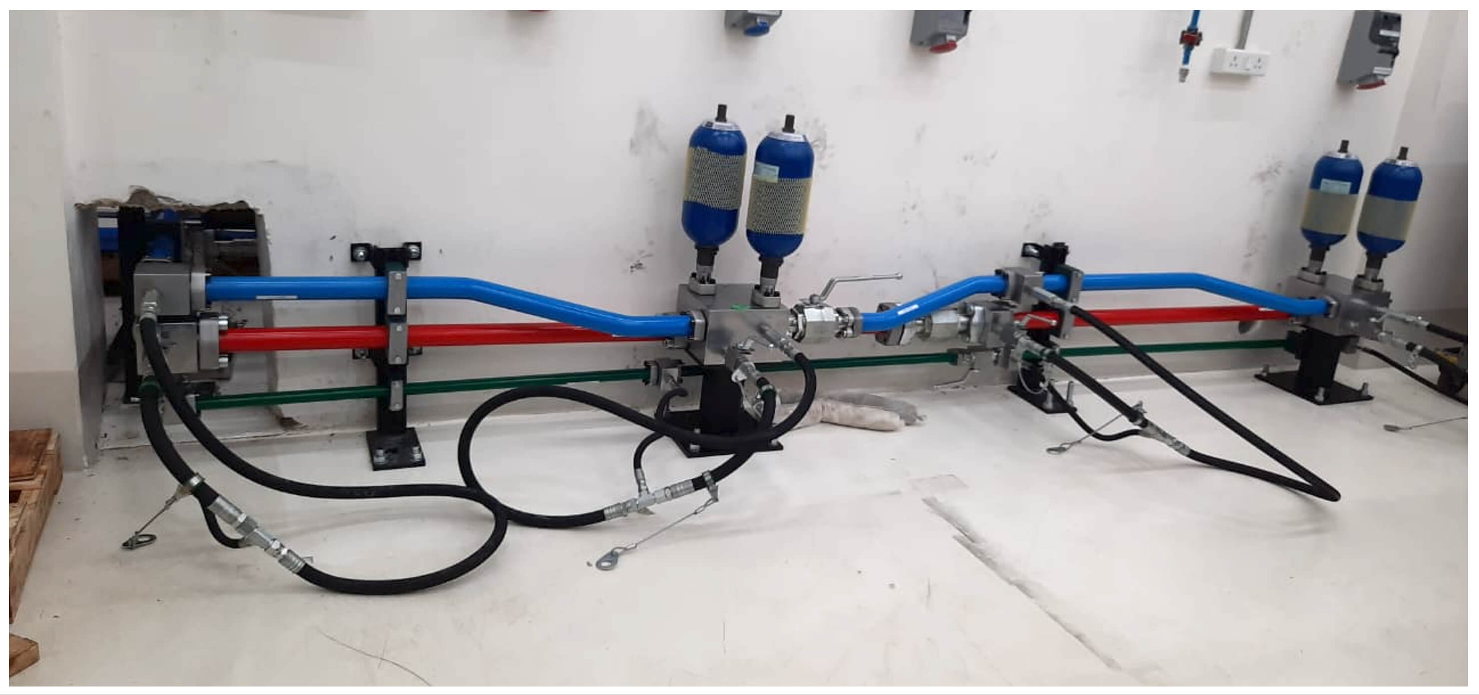
Installation: The pre-fabricated spools were installed at site, supports were procured locally

(Left) Hardline routed through the wall cut-out between HPU Room and Test Rig Area.(Right) Manifold blocks with flange ports to accomodate accumulator connection.
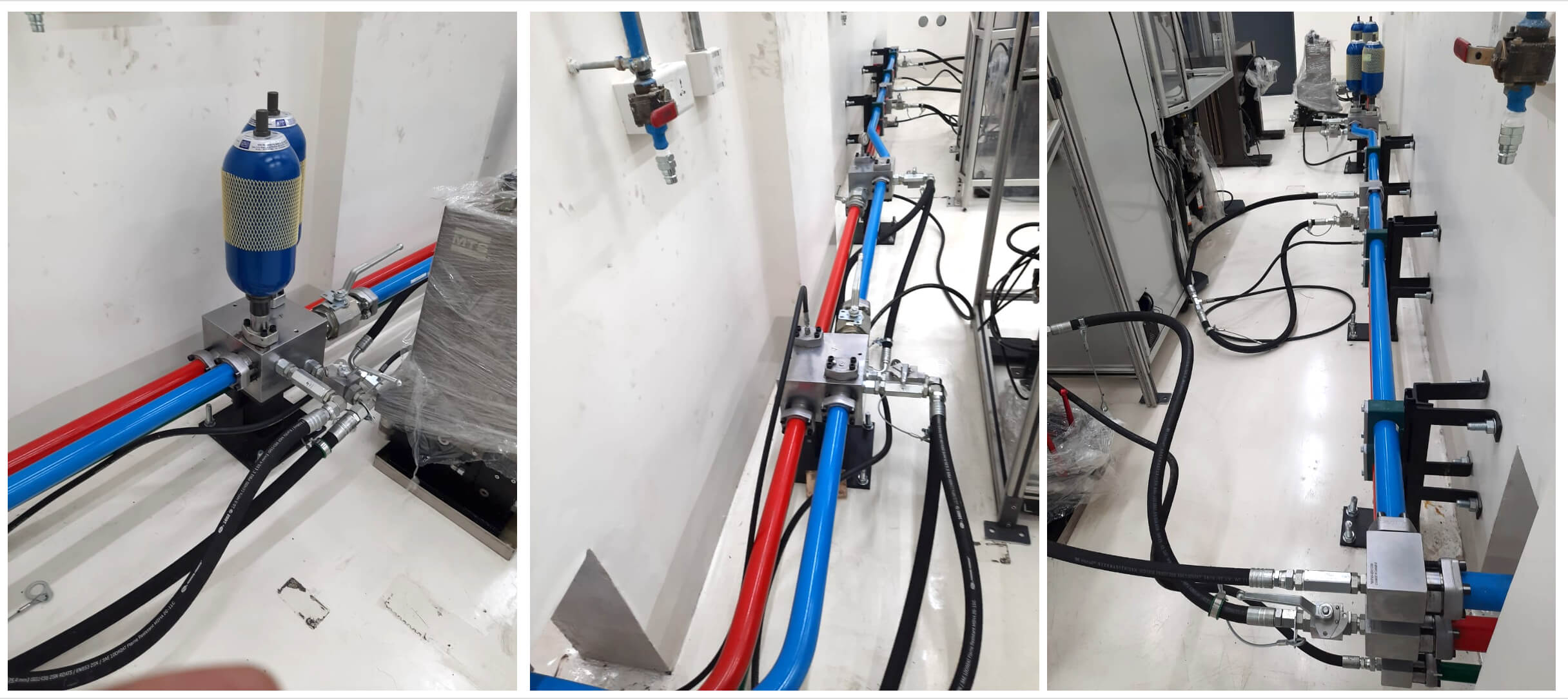
The piping was supported as per the drawing.
The piping joints were torqued to the required value after completion of the pipe erection and before doing the pressure test.
- Pressure Testing: The installed pipes were Pressure tested to 1.5 x system working pressure with hydraulic oil and was witnessed.
-
Flushing: Flushing was done to a cleanliness level which was many notches cleaner than the required cleanliness level.
- Commissioning and Handover: After completion of flushing activity, the flushing loops were dismantled and reconnected to the respective equipment ports. The reassembled joints were re-torqued to the required value and the system equipments were run. The customer positively acknowledged the job with signed reports after successful commissioning.
Download the Project E-Book
DOWNLOAD E-BOOK
